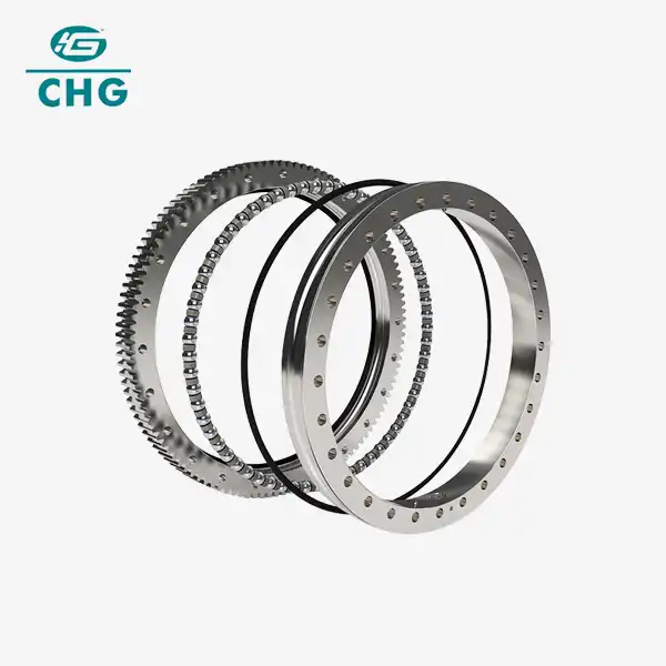
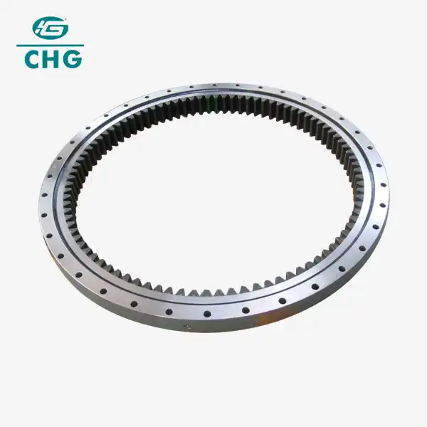
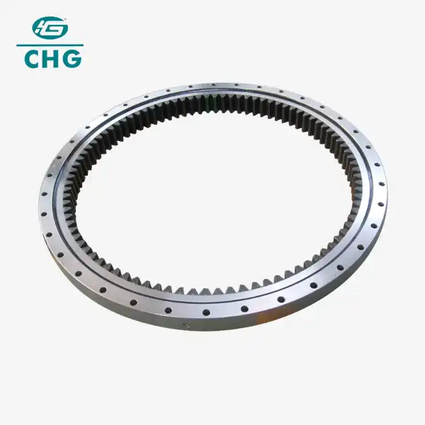
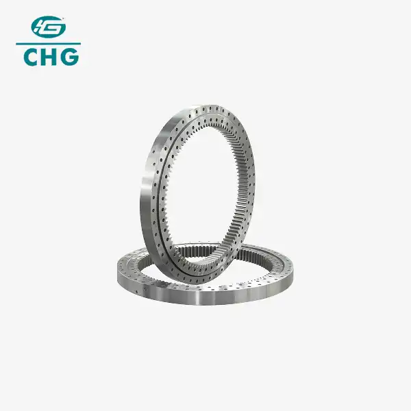
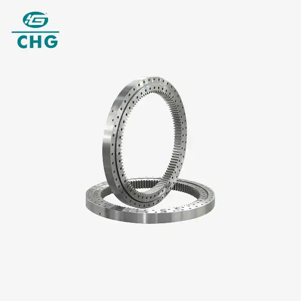
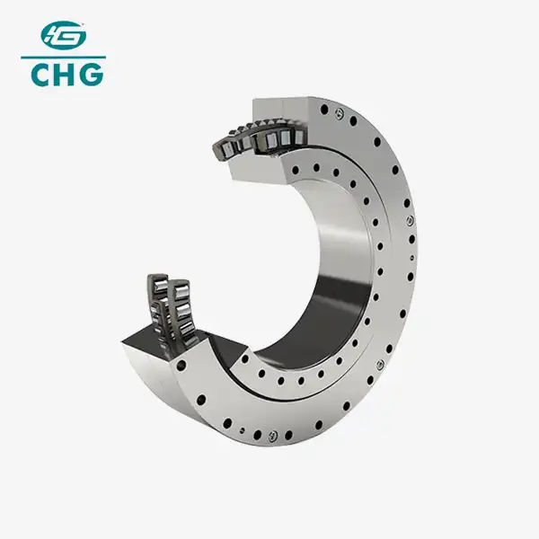
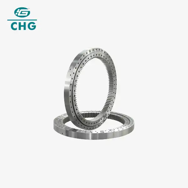
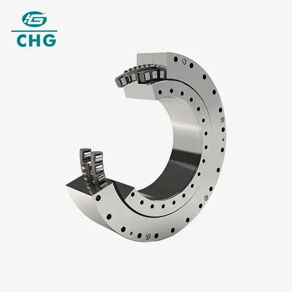
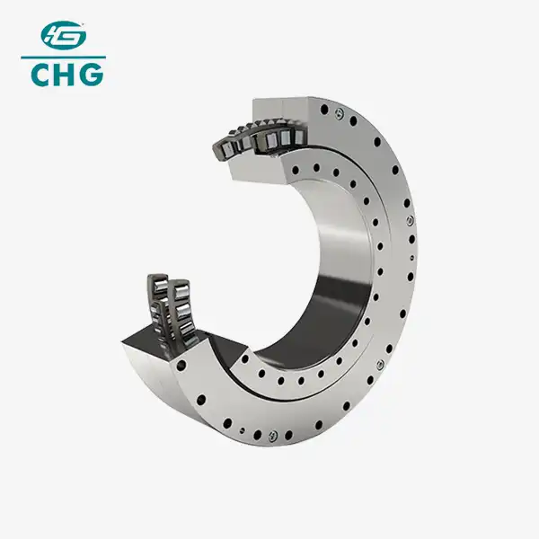
Four Point Contact Ball Slewing Bearing
2. Size: For No Gear Type
Inner Diameter: 260-4272mm ,Outer Diameter: 480-4726mm
Weight: 55-4000kg
For Internal Gear Type
Inner Diameter: 458-4272mm ,Outer Diameter:662-4726mm
Weight: 94-4000kg
For External Gear Type
Inner Diameter: 470-4272mm ,Outer Diameter: 694-4726mm
Weight: 93.1-4000kg
3. Feature: Four-point contact ball slewing bearings contact angle is usually 35°. If there is only a radial load, each steel ball contacts the raceway at four points. If there is only a unidirectional axial load, each steel ball contacts the raceway at two points. It can bear axial loads in two directions as well as a certain eccentric load, i.e. torque. Such kind of bearing has features and properties of both single-row and double-row angular contact ball bearings. If it is used in a high-speed scenario, two-point contact must be ensured for its normal working.
4. Material:50Mn/42CrMo/S48C/42CrMo4/16Mn
Product Details
Welcome to the ultimate guide on Four Point Contact Ball Slewing Bearings. Whether you're in construction, lifting machinery, wind power generation, or any other sector that requires precision rotation and load-bearing capabilities, this comprehensive product page is designed to help you understand the benefits and applications of the slewing bearings. As a professional in the industry, you'll find all the information you need to make an informed decision for your equipment.
What is a Four Point Contact Ball Slewing Bearing?
A Four Point Contact Ball Slewing Bearing is a type of bearing that allows for smooth rotation between two components while supporting high axial, radial, and tilting loads. The design includes four points of contact where balls touch the raceways, which helps distribute loads evenly and ensures stability and longevity. This bearing is crucial in applications requiring precise rotational movement and high load capacities.
Key Features:
- High Load Capacity: Supports substantial axial and radial loads.
- Precision Rotation: Ensures smooth and accurate movement.
- Durability: Designed for long-lasting performance in various working conditions.
- Versatility: Suitable for a wide range of applications, from construction machinery to medical equipment.
Why Choose CHG Bearing?
Customized Solutions
At CHG Bearing, we understand that every application is unique. We offer tailored solutions to meet the specific requirements of different working conditions. Our team of experts is dedicated to providing bearings that fit your exact needs.
Industry Experience
With over 30 years of experience in the bearing industry, CHG Bearing has established a reputation for quality and reliability. We have partnered with numerous large companies and continue to innovate to meet the evolving demands of the market.
Patents and Certifications
Our commitment to quality is reflected in our extensive portfolio of over 50 invention patents and certifications, including ISO9001 for quality management and ISO14001 for environmental management. These certifications ensure that our products meet the highest standards of performance and reliability.
Feel free to contact us at [sale@chg-bearing.com] for any inquiries or customized solutions.

Technical Specifications
| Specification | Details |
|---|---|
| Type | Four Point Contact Ball Slewing Bearing |
| Load Capacity | Axial: High; Radial: High; Tilting: Medium |
| Material | High-strength steel, stainless steel options |
| Precision Class | P0, P6, P5, P4 |
| Temperature Range | -40°C to +80°C |
| Certification | ISO9001, ISO14001 |
| Customization | Available based on requirements |
Benefits of Four Point Contact Ball Slewing Bearing
- Enhanced Load Distribution: Four-point contact design allows for even distribution of loads, reducing wear and extending bearing life.
- Smooth Operation: Precision ball arrangement ensures smooth and reliable rotation.
- Versatility: Ideal for various industries, including construction, lifting machinery, and more.
- Durability: High-quality materials and design contribute to a long service life.
Applications
- Construction Machinery: Used in excavators, loaders, bulldozers, and graders for rotational and load-bearing functions.
- Lifting Machinery: Essential in tower cranes, gantry cranes, and truck cranes for rotation and stability.
- Wind Power Generation: Supports the rotating part of wind turbine cabins for optimal wind energy capture.
- Oil Drilling: Withstands high loads from all directions in drilling rigs.
- Military Equipment: Provides flexible rotation for tanks and armored vehicles.
- Port Terminals: Enhances the efficiency of loading and unloading equipment.
- Agricultural Machinery: Improves rotation in harvesters and tractors.
- Medical Equipment: Facilitates rotation in devices like MRI machines.
- Amusement Facilities: Ensures smooth rotation in carousels and Ferris wheels.
- Aerospace: Supports rotation in satellites and rockets.
- Material Processing Machinery: Useful in various machinery for accurate processing.
Installation Guide
- Preparation: Ensure the installation area is clean and free from debris.
- Alignment: Align the bearing with the mounting holes and ensure it is centered.
- Mounting: Secure the bearing using appropriate fasteners and torque specifications.
- Lubrication: Apply the recommended lubricant to ensure smooth operation.
- Testing: Rotate the bearing manually to check for any misalignment or issues.
Maintenance and Care
- Regular Inspection: Check for signs of wear, such as noise or vibration.
- Lubrication: Keep the bearing properly lubricated according to manufacturer recommendations.
- Cleaning: Keep the bearing and surrounding area clean to prevent contamination.
- Monitoring: Monitor the performance and address any issues promptly to prevent damage.

FAQ
Q: What industries benefit from for the products?
A: Industries include construction, lifting machinery, wind power, oil drilling, military, ports, agriculture, medical, amusement, aerospace, and more.
Q: How do I choose the right the products?
A: Consider load capacity, precision requirements, material, and operating conditions. Contact us for customized recommendations.
Q: What maintenance is required for these bearings?
A: Regular inspection, lubrication, and cleaning are essential to ensure optimal performance and longevity.
Q: Can CHG Bearing provide custom solutions?
A: Yes, we offer tailored solutions to meet specific requirements and working conditions.
Customer Reviews
“CHG Bearing provided us with the perfect four point contact ball slewing bearings for our construction equipment. Their expertise and customization options made a significant difference in our project’s success.” – John D., Equipment Manager
“The quality and reliability of CHG Bearing’s products are unmatched. We’ve seen consistent performance and durability in our wind turbines.” – Sarah M., Wind Power Engineer

Contact Us
For more information or to request a quote, please contact us at sale@chg-bearing.com. Our team is ready to assist you with all your Double Row Ball Slewing Bearing needs.
Features
The Single-row Four-point Contact Ball Slewing Bearing consists of two seating rings. It is characterized by compact structure, light weight and four-point contact between the steel balls and the arc raceway. It can bear axial force, radial force and overturning moment simultaneously. It is applicable to the engineering machinery, such as slewing conveyors, welding manipulators, small-and-medium cranes, and excavators.
Note:
1.n1 is the number of oil holes, equally spaced, with oil cup M10×1 JB/T7940.1-TB7940.2
2.The mounting hole n-Φ can be replaced by the threaded hole; the tooth width b can be changed to H-h
3.The tangential force of internal gear is the maximum tangential force; the rating tangential force is half of the maximum tangential force
4.The displacement coefficient of internal tooth follows the design of external teeth.
Bearing Model | Dimensions | Mounting Dimensions | Structural Dimension | Gear data | weight (kg) | |||||||||||||||
Dmm | dmm | Hmm | D1mm | D2mm | n | mm | dmmm | Lmm | n1 | D3mm | d1mm | HImm | hmm | bmm | x | Mmm | Demm | z | ||
013.25.315 | 408 | 222 | 70 | 372 | 258 | 20 | 18 | M16 | 32 | 2 | 316 | 314 | 60 | 10 | 50 | 0 | 5 | 190 | 40 | 49 |
013.25.355 | 448 | 262 | 70 | 412 | 298 | 20 | 18 | M16 | 32 | 2 | 356 | 354 | 60 | 10 | 50 | 0 | 5 | 235 | 49 | 54 |
013.25.400 | 493 | 307 | 70 | 457 | 343 | 20 | 18 | M16 | 32 | 2 | 401 | 399 | 60 | 10 | 50 | 0 | 6 | 276 | 48 | 62 |
013.25.450 | 543 | 357 | 70 | 507 | 393 | 20 | 18 | M16 | 32 | 2 | 451 | 449 | 60 | 10 | 50 | 0 | 6 | 324 | 56 | 71 |
013.30.500 | 602 | 398 | 80 | 566 | 434 | 20 | 18 | M16 | 32 | 4 | 501 | 498 | 70 | 10 | 60 | 0.5 | 5 | 367 | 74 | 85 |
014.30.500 | 6 | 368.4 | 62 | |||||||||||||||||
013.25.500 | 602 | 398 | 80 | 566 | 434 | 20 | 18 | M16 | 32 | 4 | 501 | 499 | 70 | 10 | 60 | 0.5 | 5 | 367 | 74 | 85 |
014.25.500 | 6 | 368.4 | 62 | |||||||||||||||||
013.30.560 | 662 | 458 | 80 | 626 | 494 | 20 | 18 | M16 | 32 | 4 | 561 | 558 | 70 | 10 | 60 | 0.5 | 5 | 427 | 86 | 95 |
014.30.560 | 6 | 428.4 | 72 | |||||||||||||||||
013.25.560 | 662 | 458 | 80 | 626 | 494 | 20 | 18 | M16 | 32 | 4 | 561 | 559 | 70 | 10 | 60 | 0.5 | 5 | 427 | 86 | 95 |
014.25.560 | 6 | 428.4 | 72 | |||||||||||||||||
013.30.630 | 732 | 528 | 80 | 696 | 564 | 24 | 18 | M16 | 32 | 4 | 631 | 628 | 70 | 10 | 60 | 0.5 | 6 | 494.4 | 83 | 110 |
014.30.630 | 8 | 491.2 | 62 | |||||||||||||||||
013.25.630 | 732 | 528 | 80 | 696 | 564 | 24 | 18 | M16 | 32 | 4 | 631 | 629 | 70 | 10 | 60 | 0.5 | 6 | 494.4 | 83 | 110 |
014.25.630 | 8 | 491.2 | 62 | |||||||||||||||||
013.30.710 | 812 | 608 | 80 | 776 | 644 | 24 | 18 | M16 | 32 | 4 | 711 | 708 | 70 | 10 | 60 | 0.5 | 6 | 572.4 | 96 | 120 |
014.30.710 | 8 | 571.2 | 72 | |||||||||||||||||
013.25.710 | 812 | 608 | 80 | 776 | 644 | 24 | 18 | M16 | 32 | 4 | 711 | 709 | 70 | 10 | 60 | 0.5 | 6 | 572.4 | 96 | 120 |
014.25.710 | 8 | 571.2 | 72 | |||||||||||||||||
013.40.800 | 922 | 678 | 100 | 878 | 722 | 30 | 22 | M20 | 40 | 6 | 801 | 798 | 90 | 10 | 80 | 0.5 | 8 | 635.2 | 80 | 220 |
014.40.800 | 10 | 634 | 64 | |||||||||||||||||
013.30.800 | 922 | 678 | 100 | 878 | 722 | 30 | 22 | M20 | 40 | 6 | 801 | 798 | 90 | 10 | 80 | 0.5 | 8 | 635.2 | 80 | 220 |
014.30.800 | 10 | 634 | 64 | |||||||||||||||||
013.40.900 | 1022 | 778 | 100 | 978 | 822 | 30 | 22 | M20 | 40 | 6 | 901 | 898 | 90 | 10 | 80 | 0.5 | 8 | 739.2 | 93 | 240 |
014.40.900 | 10 | 734 | 74 | |||||||||||||||||
013.30.900 | 1022 | 778 | 100 | 978 | 822 | 30 | 22 | M20 | 40 | 6 | 901 | 898 | 90 | 10 | 80 | 0.5 | 8 | 739.2 | 93 | 240 |
014.30.900 | 10 | 734 | 74 | |||||||||||||||||
013.40.1000 | 1122 | 878 | 100 | 1078 | 922 | 36 | 22 | M20 | 40 | 6 | 1001 | 998 | 90 | 10 | 80 | 0.5 | 10 | 824 | 83 | 270 |
014.40.1000 | 12 | 820.8 | 69 | |||||||||||||||||
013.30.1000 | 1122 | 878 | 100 | 1078 | 922 | 36 | 22 | M20 | 40 | 6 | 1001 | 998 | 90 | 10 | 80 | 0.5 | 10 | 824 | 83 | 270 |
014.30.1000 | 12 | 820.8 | 69 | |||||||||||||||||
013.40.1120 | 1242 | 998 | 100 | 1198 | 1042 | 36 | 22 | M20 | 40 | 6 | 1121 | 1118 | 90 | 10 | 80 | 0.5 | 10 | 944 | 95 | 300 |
014.40.1120 | 12 | 940.8 | 79 | |||||||||||||||||
013.30.1120 | 1242 | 998 | 100 | 1198 | 1042 | 36 | 22 | M20 | 40 | 6 | 1121 | 1118 | 90 | 10 | 80 | 0.5 | 10 | 944 | 95 | 300 |
014.30.1120 | 12 | 940.8 | 79 | |||||||||||||||||
013.45.1250 | 1390 | 1110 | 110 | 1337 | 1163 | 40 | 26 | M24 | 48 | 5 | 1252 | 1248 | 100 | 10 | 90 | 0.5 | 12 | 1049 | 88 | 420 |
014.45.1250 | 14 | 1042 | 75 | |||||||||||||||||
013.35.1250 | 1390 | 1110 | 110 | 1337 | 1163 | 40 | 26 | M24 | 48 | 5 | 1251 | 1248 | 100 | 10 | 90 | 0.5 | 12 | 1049 | 88 | 420 |
014.35.1250 | 14 | 11042 | 75 | |||||||||||||||||
Features
The Single-row Four-point Contact Ball Slewing Bearing consists of two seating rings. It is characterized by compact structure, light weight and four-point contact between the steel balls and the arc raceway. It can bear axial force, radial force and overturning moment simultaneously. It is applicable to the engineering machinery, such as slewing conveyors, welding manipulators, small-and-medium cranes, and excavators.
Note:
1.n1 is the number of oil holes, equally spaced, with oil cup M10×1 JB/T7940.1-TB7940.2
2.The mounting hole n-Φ can be replaced by the threaded hole; the tooth width b can be changed to H-h
Bearing Model | Dimensions | Mounting Dimensions | Structural Dimension | weight (kg) | |||||||||||
Dmm | dmm | Hmm | D1mm | D2mm | n | mm | dmmm | Lmm | n1 | D3mm | d1mm | H1mm | hmm | ||
010.20.200 | 280 | 120 | 60 | 248 | 152 | 12 | 16 | M14 | 28 | 2 | 201 | 199 | 50 | 10 | 20 |
010.20.224 | 304 | 144 | 60 | 272 | 176 | 12 | 16 | M14 | 28 | 2 | 225 | 223 | 50 | 10 | 22 |
010.20.250 | 330 | 170 | 60 | 298 | 202 | 18 | 16 | M14 | 28 | 2 | 251 | 249 | 50 | 10 | 25 |
010.20.280 | 360 | 200 | 60 | 328 | 232 | 18 | 16 | M14 | 28 | 2 | 281 | 279 | 50 | 10 | 28 |
010.25.315 | 408 | 222 | 70 | 372 | 258 | 20 | 18 | M16 | 32 | 2 | 316 | 314 | 60 | 10 | 44 |
010.25.355 | 448 | 262 | 70 | 412 | 298 | 20 | 18 | M16 | 32 | 2 | 356 | 354 | 60 | 10 | 49 |
010.25.400 | 493 | 307 | 70 | 457 | 343 | 20 | 18 | M16 | 32 | 2 | 401 | 399 | 60 | 10 | 56 |
010.25.450 | 543 | 357 | 70 | 507 | 393 | 20 | 18 | M16 | 32 | 2 | 451 | 449 | 60 | 10 | 62 |
010.30.500 | 602 | 398 | 80 | 566 | 434 | 20 | 18 | M16 | 32 | 4 | 501 | 498 | 70 | 10 | 85 |
01025.500 | 1602 | 398 | 80 | 566 | 434 | 20 | 18 | M16 | 32 | 4 | 501 | 499 | 70 | 10 | 85 |
010.30.560 | 662 | 458 | 80 | 626 | 494 | 20 | 18 | M16 | 32 | 4 | 561 | 558 | 70 | 10 | 95 |
010.25.560 | 662 | 458 | 80 | 626 | 494 | 20 | 18 | M16 | 32 | 4 | 561 | 559 | 70 | 10 | 95 |
010.30.630 | 732 | 528 | 80 | 696 | 564 | 24 | 18 | M16 | 32 | 4 | 631 | 628 | 70 | 10 | 110 |
010.25.630 | I732 | 528 | 80 | 696 | 564 | 24 | 18 | M16 | 32 | 4 | 631 | 629 | 70 | 10 | 110 |
010.30.710 | 812 | 608 | 80 | 776 | 644 | 24 | 18 | M16 | 32 | 4 | 711 | 708 | 70 | 10 | 120 |
010.25.710 | 812 | 608 | 80 | 776 | 644 | 24 | 18 | M16 | 32 | 4 | 711 | 709 | 70 | 10 | 120 |
010.40.800 | 922 | 678 | 100 | 878 | 722 | 30 | 22 | M20 | 40 | 6 | 801 | 798 | 90 | 10 | 220 |
010.30.800 | 922 | 678 | 100 | 878 | 722 | 30 | 22 | M20 | 40 | 6 | 801 | 798 | 90 | 10 | 220 |
010.40.900 | 1022 | 778 | 100 | 978 | 822 | 30 | 22 | M20 | 40 | 6 | 901 | 898 | 90 | 10 | 240 |
010.30.900 | 1022 | 778 | 100 | 978 | 822 | 30 | 22 | M20 | 40 | 6 | 901 | 898 | 90 | 10 | 240 |
010.40.1000 | 1122 | 878 | 100 | 1078 | 922 | 36 | 22 | M20 | 40 | 6 | 1001 | 998 | 90 | 10 | 270 |
010.30.1000 | 1122 | 878 | 100 | 1078 | 922 | 36 | 22 | M20 | 40 | 6 | 1001 | 998 | 90 | 10 | 270 |
010.40.1120 | 1242 | 998 | 100 | 1198 | 1042 | 36 | 22 | M20 | 40 | 6 | 1121 | 1118 | 90 | 10 | 300 |
010.30.1120 | 1242 | 998 | 100 | 1198 | 1042 | 36 | 22 | M20 | 40 | 6 | 1121 | 1118 | 90 | 10 | 300 |
010.45.1250 | 1390 | 1110 | 110 | 1337 | 1163 | 40 | 26 | M24 | 48 | 5 | 1252 | 1248 | 100 | 10 | 420 |
010.35.1250 | 1390 | 1110 | 110 | 1337 | 1163 | 40 | 26 | M24 | 48 | 5 | 1251 | 1248 | 100 | 10 | 420 |
010.45.1400 | 1540 | 1260 | 110 | 1487 | 1313 | 40 | 26 | M24 | 48 | 5 | 1402 | 1398 | 100 | 10 | 480 |
010.35.1400 | 1540 | 1260 | 110 | 1487 | 1313 | 40 | 26 | M24 | 48 | 5 | 1401 | 1398 | 100 | 10 | 480 |
011.45.1600 | 1740 | 1460 | 110 | 1687 | 1513 | 45 | 26 | M24 | 48 | 5 | 1602 | 1598 | 100 | 10 | 550 |
010.35.1600 | 1740 | 1460 | 110 | 1687 | 1513 | 45 | 26 | M24 | 48 | 5 | 1601 | 1598 | 100 | 10 | 550 |
010.45.1800 | 1940 | 1660 | 110 | 1887 | 1713 | 45 | 26 | M24 | 48 | 5 | 1802 | 1798 | 100 | 10 | 610 |
010.35.1800 | 1940 | 1660 | 110 | 1887 | 1713 | 45 | 26 | M24 | 48 | 5 | 1801 | 1798 | 100 | 10 | 610 |
010.60.2000 | 2178 | 1825 | 144 | 2110 | 1891 | 48 | 33 | M30 | 60 | 8 | 2002 | 1998 | 132 | 12 | 1100 |
010.40.2000 | 2178 | 1825 | 144 | 2110 | 1891 | 48 | 33 | M30 | 60 | 8 | 2001 | 1998 | 132 | 12 | 1100 |
010.60.2240 | 2418 | 2065 | 144 | 2350 | 2131 | 48 | 33 | M30 | 60 | 8 | 2242 | 2238 | 132 | 12 | 1250 |
010.40.2240 | 2418 | 2065 | 144 | 2350 | 2131 | 48 | 33 | M30 | 60 | 8 | 2241 | 2238 | 132 | 12 | 1250 |
010.60.2500 | 2678 | 2325 | 144 | 2610 | 2391 | 56 | 33 | M30 | 60 | 8 | 2502 | 2498 | 132 | 12 | 1400 |
010.40.2500 | 2678 | 2325 | 144 | 2610 | 2391 | 56 | 33 | M30 | 60 | 8 | 2501 | 2498 | 132 | 12 | 1400 |
010.60.2800 | 2978 | 2625 | 144 | 2910 | 2691 | 56 | 33 | M30 | 60 | 8 | 2802 | 2798 | 132 | 12 | 1600 |
010.40.2800 | 2978 | 2625 | 144 | 2910 | 2691 | 56 | 33 | M30 | 60 | 8 | 2802 | 2798 | 132 | 12 | 1600 |
010.75.3150 | 3376 | 2922 | 174 | 3286 | 3014 | 56 | 45 | M42 | 84 | 8 | 3152 | 3147 | 162 | 12 | 2800 |
010.50.3150 | 3376 | 2922 | 174 | 3286 | 3014 | 56 | 45 | M42 | 84 | 8 | 3152 | 3147 | 162 | 12 | 2800 |
010.75.3550 | 3776 | 3322 | 174 | 3686 | 3014 | 56 | 45 | M42 | 84 | 8 | 3552 | 3547 | 162 | 12 | 3500 |
010.50.3550 | 3776 | 3322 | 174 | 3686 | 3014 | 56 | 45 | M42 | 84 | 10 | 3552 | 3548 | 162 | 12 | 3500 |
010.75.4000 | 4226 | 3772 | 174 | 4136 | 3864 | 60 | 45 | M42 | 84 | 10 | 4002 | 3997 | 162 | 12 | 4200 |
010.50.4000 | 4226 | 3772 | 174 | 4136 | 3864 | 60 | 45 | M42 | 84 | 10 | 4002 | 3998 | 162 | 12 | 4200 |
010.75.4500 | 4726 | 4272 | 174 | 4636 | 4364 | 60 | 45 | M42 | 84 | 10 | 4502 | 4497 | 162 | 12 | 5100 |
010.50.4500 | 4726 | 4272 | 174 | 4636 | 4364 | 60 | 45 | M42 | 84 | 10 | 4502 | 4498 | 162 | 12 | 5100 |
Features
The Single-row Four-point Contact Ball Slewing Bearing consists of two seating rings. It is characterized by compact structure, light weight and four-point contact between the steel balls and the arc raceway. It can bear axial force, radial force and overturning moment simultaneously. It is applicable to the engineering machinery, such as slewing conveyors, welding manipulators, small-and-medium cranes, and excavators.
Note:
1.n1 is the number of oil holes, equally spaced, with oil cup M10×1 JB/T7940.1-TB7940.2
2.The mounting hole n-Φ can be replaced by the threaded hole; the tooth width b can be changed to H-h
Bearing Model | Dimensions | Mounting Dimensions | Structural Dimension | Gear data | weight (kg) | |||||||||||||||
Dmm | dmm | Hmm | D1mm | D2mm | n | omm | dmmm | Lmm | n1 | D3mm | d1mm | H1mm | hmm | bmm | x | Mmm | Demm | z | ||
011.45.1400 | 1540 | 1260 | 110 | 1487 | 1313 | 40 | 26 | M24 | 48 | 5 | 1402 | 1398 | 100 | 10 | 90 | 0.5 | 12 | 1605.6 | 131 | 480 |
012.45.1400 | 14 | 1607.2 | 112 | |||||||||||||||||
011.35.1400 | 1540 | 1260 | 110 | 1487 | 1313 | 40 | 26 | M24 | 48 | 5 | 1401 | 1398 | 100 | 10 | 90 | 0.5 | 12 | 1605.6 | 131 | 480 |
012.35.1400 | 14 | 1607.2 | 112 | |||||||||||||||||
011.45.1600 | 1740 | 1460 | 110 | 1687 | 1513 | 45 | 26 | M24 | 48 | 5 | 1602 | 1598 | 100 | 10 | 90 | 0.5 | 14 | 1817.2 | 127 | 550 |
012.45.1600 | 16 | 1820.8 | 111 | |||||||||||||||||
011.35.1600 | 1740 | 1460 | 110 | 1687 | 1513 | 45 | 26 | M24 | 48 | 5 | 1601 | 1598 | 100 | 10 | 90 | 0.5 | 14 | 1817.2 | 127 | 550 |
012.35.1600 | 16 | 1820.8 | 111 | |||||||||||||||||
011.45.1800 | 1940 | 1660 | 110 | 1887 | 1713 | 45 | 26 | M24 | 48 | 5 | 1802 | 1798 | 100 | 10 | 90 | 0.5 | 14 | 2013.2 | 141 | 610 |
012.45.1800 | 16 | 2012.8 | 123 | |||||||||||||||||
011.35.1800 | 1940 | 1660 | 110 | 1887 | 1713 | 45 | 26 | M24 | 48 | 5 | 1801 | 1798 | 100 | 10 | 90 | 0.5 | 14 | 2013.2 | 141 | 610 |
012.35.1800 | 16 | 2012.8 | 123 | |||||||||||||||||
011.60.2000 | 2178 | 1825 | 144 | 2110 | 1891 | 48 | 33 | M30 | 60 | 8 | 2002 | 1998 | 132 | 12 | 120 | 0.5 | 16 | 2268.8 | 139 | 1100 |
012.60.2000 | 18 | 2264.4 | 123 | |||||||||||||||||
011.40.2000 | 2178 | 1825 | 144 | 2110 | 1891 | 48 | 33 | M30 | 60 | 8 | 2001 | 1998 | 132 | 12 | 120 | 0.5 | 16 | 2268.8 | 139 | 1100 |
012.40.2000 | 18 | 2264.4 | 123 | |||||||||||||||||
011.60.2240 | 2418 | 2065 | 144 | 2350 | 2131 | 48 | 33 | M30 | 60 | 8 | 2242 | 2238 | 132 | 12 | 120 | 0.5 | 16 | 2492.8 | 153 | 1250 |
012.60.2240 | 18 | 2498.4 | 136 | |||||||||||||||||
011.40.2240 | 2418 | 2065 | 144 | 2350 | 2131 | 48 | 33 | M30 | 60 | 8 | 2241 | 2238 | 132 | 12 | 120 | 0.5 | 16 | 2492.8 | 153 | 1250 |
012.40.2240 | 18 | 2498.4 | 136 | |||||||||||||||||
011.60.2500 | 2678 | 2325 | 144 | 2610 | 2391 | 56 | 33 | M30 | 60 | 8 | 2502 | 2498 | 132 | 12 | 120 | 0.5 | 18 | 2768.4 | 151 | 1400 |
012.60.2500 | 20 | 2776 | 136 | |||||||||||||||||
011.40.2500 | 2678 | 2325 | 144 | 2610 | 2391 | 56 | 33 | M30 | 60 | 8 | 2501 | 2498 | 132 | 12 | 120 | 0.5 | 18 | 2768.4 | 151 | 1400 |
012.40.2500 | 20 | 2776 | 136 | |||||||||||||||||
011.60.2800 | 2978 | 2625 | 144 | 2910 | 2691 | 56 | 33 | M30 | 60 | 8 | 2802 | 2798 | 132 | 12 | 120 | 0.5 | 18 | 3074.4 | 168 | 1600 |
012.60.2800 | 20 | 3076 | 151 | |||||||||||||||||
011.40.2800 | 2978 | 2625 | 144 | 2910 | 2691 | 56 | 33 | M30 | 60 | 8 | 2802 | 2798 | 132 | 12 | 120 | 0.5 | 18 | 3074.4 | 168 | 1600 |
012.40.2800 | 20 | 3076 | 151 | |||||||||||||||||
011.75.3150 | 3376 | 2922 | 174 | 3286 | 3014 | 56 | 45 | M42 | 84 | 8 | 3152 | 3147 | 162 | 12 | 150 | 0.5 | 20 | 3476 | 171 | 2800 |
012.75.3150 | 22 | 3471.6 | 155 | |||||||||||||||||
011.50.3150 | 3376 | 2922 | 174 | 3286 | 3014 | 56 | 45 | M42 | 84 | 8 | 3152 | 3147 | 162 | 12 | 150 | 0.5 | 20 | 3476 | 171 | 2800 |
012.50.3150 | 22 | 3471.6 | 155 | |||||||||||||||||
011.75.3550 | 3776 | 3322 | 174 | 3686 | 3014 | 56 | 45 | M42 | 84 | 8 | 3552 | 3547 | 162 | 12 | 150 | 0.5 | 20 | 3876 | 191 | 3500 |
012.75.3550 | 22 | 3889.6 | 174 | |||||||||||||||||
011.50.3550 | 3776 | 3322 | 174 | 3686 | 3014 | 56 | 45 | M42 | 84 | 10 | 3552 | 3548 | 162 | 12 | 150 | 0.5 | 20 | 3876 | 191 | 3500 |
012.50.3550 | 22 | 3889.6 | 174 | |||||||||||||||||
011.75.4000 | 4226 | 3772 | 174 | 4136 | 3864 | 60 | 45 | M42 | 84 | 10 | 4002 | 3997 | 162 | 12 | 150 | 0.5 | 22 | 4329.6 | 194 | 4200 |
012.75.4000 | 25 | 4345 | 171 | |||||||||||||||||
011.50.4000 | 4226 | 3772 | 174 | 4136 | 3864 | 60 | 45 | M42 | 84 | 10 | 4002 | 3998 | 162 | 12 | 150 | 0.5 | 22 | 4329.6 | 194 | 4200 |
012.50.4000 | 25 | 4345 | 171 | |||||||||||||||||
011.75.4500 | 4726 | 4272 | 174 | 4636 | 4364 | 60 | 45 | M42 | 84 | 10 | 4502 | 4497 | 162 | 12 | 150 | 0.5 | 22 | 4835.6 | 217 | 5100 |
012.75.4500 | 25 | 4845 | 191 | |||||||||||||||||
011.50.4500 | 4726 | 4272 | 174 | 4636 | 4364 | 60 | 45 | M42 | 84 | 10 | 4502 | 4498 | 162 | 12 | 150 | 0.5 | 22 | 4835.6 | 217 | 5100 |
012.50.4500 | 25 | 4845 | 191 | |||||||||||||||||
